01 / 23
Drawing and onboarding
Guidance connects drawing, nesting and production.
mCAD · Drawing and onboardingYINGFENG
Actual mCAD UI / offline production components
Connect mCAD drawing and learned nesting strategies with toolpaths, production planning and live monitoring. Bring operator experience and machine constraints into one continuous workflow.
Follow the drawing, nesting and job-planning workflows relevant to your parts and machines.
When drawings, quantities and machine settings are handled separately, a compact layout may still be impossible to cut. Shared rails, head travel, physical spacing and tool processes need to be checked together.
↗02Open outlines, incorrect dimensions or missing group members affect nesting. Repair the drawing, then recognize and save useful manually placed groups for later complete-group reuse and remaining single parts.
↗03Rapid travel, waiting, tool lift and lowering, curve speed and head coordination all affect cutting time. Material utilization alone misses batch counts and actual process conditions.
↗04Large regular parts, different contours or narrow gaps can restrict parallel work. Non-cutting heads remain physical objects and need reachable parking positions and avoidance checks.
↗05An import, a visible layout or a Send click does not by itself prove correct dimensions, valid routes or a saved host job. Review the current result and actual receipts at each step.
↗Download mCAD and create separate projects with the real dimensions of your regular parts. Compare machine models and head counts with the same sheet, requested quantities, spacing and allowed angles.
Import regular drawings or draw at actual millimetre dimensions; check closed outlines and internal holes or slots.
Create a separate project for each machine configuration and set sheet size, physical head count, participating heads, margins and spacing.
Nest the same parts by quantity or fill-sheet mode; record actual nested counts and inspect head assignments.
Pass each project’s safety check and generate dynamic toolpaths; compare estimated time, parallel head use, waiting and rapid travel.
Review shared-rail, physical head spacing and actual travel constraints, then compare additional heads with a lower head count.
A denser layout or more heads alone cannot prove faster cutting. Compare successfully planned current results with confirmed material thickness, tools, speed mode, shared rail and travel limits.
Doubling the head count does not guarantee double productivity. If large regular parts cannot synchronize within shared-axis and safety-spacing constraints, fewer heads may suit them better. Standalone estimates support comparison; machine selection still requires actual parameters and test cuts.
Keep materials, blades, processes, tasks and machine status connected, with an actual operating entry point for each step.
Move from drawing and nesting to machine connection, homing, task planning and production monitoring.
01Save a manually arranged multi-part combination. Reuse eligible combinations first for sheet filling and quantity-based nesting.
02After layout checks and successful planning with current parameters, inspect head assignments, toolpaths and estimates; review the current process and production task plan.
03Save tasks, completed quantities and progress for restart recovery. Prepare separate projects for different machines.
04Recall 200 material/process speed presets and use thickness, blade, depth and independent head Z work points.
05Prioritize parallel cutting within shared-rail, travel and clearance rules. Check nesting and plan paths with current parameters.
06Irregular parts need more than individual placement. Learn the arrangement you prefer, then match part features and reuse it within sheet, quantity and machine constraints.
View part and nesting images of your own strategies and delete them. Other users’ server strategies follow server state.
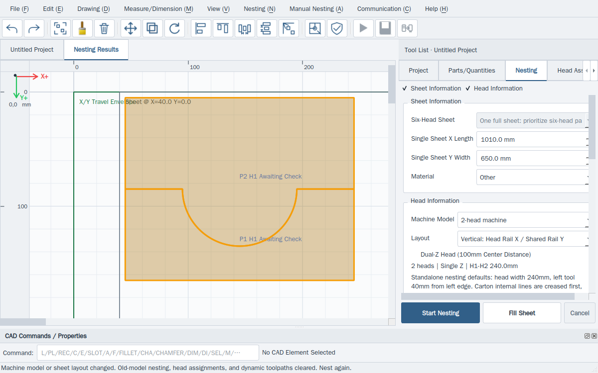
Select a step to see its operation. After nesting, the main application checks the machine, tools and shop-floor conditions.
Import the drawing or use mCAD tools. Check dimensions, contours and part names, and enter required quantities.
 Actual mCAD UI / offline production components
Set the sheet, material, heads, margins and spacing. Learn a manual combination, then fill the sheet or nest by quantity.
 Actual mCAD UI / offline production components
Complete safety checks. Inspect dynamic toolpaths, head assignments and estimated cutting time.
 Actual mCAD UI / offline production components
Save and send the nesting result to the main application. Add a production task with quantity and process settings.
 Actual mCAD UI / offline production components
Check actual controller connection and readiness, then complete machine homing. Returning to zero and homing serve different purposes.
Actual mCAD UI / offline production componentsConfirm sheet area, thickness, blade suitability and each head’s Z work point. Recall validated speed presets.
 Actual mCAD UI / offline production components
Select the task and plan successfully with current process and machine parameters, then review the route and estimated machining time.
Actual mCAD UI / offline production componentsSet the origin for the actual sheet. Check the loaded area and shop-floor conditions before confirming readiness.
Actual mCAD UI / offline production componentsStart actual production. Follow tasks, quantities, head positions and paths, with live load curves for observation.
Actual mCAD UI / offline production componentsCheck quantities and save tasks. Isolate a W/tool fault only after confirming Z is safe, then revalidate. Unresolved Z faults require stopping.
 Actual mCAD UI / offline production components
Images are from YingFeng software. Five website languages do not imply the desktop software has the same five-language interface.
A W-axis or tool fault may allow that head to be isolated after the operator confirms Z is safely raised. Replan and validate the healthy heads. Z is a critical safety axis: an unresolved Z fault requires stopping and repair. Retain records to help service teams prioritize support.
Select a head to simulate disabling it. This illustration does not control hardware; real degradation requires replanning and checks.
Keep at least one head before arranging a task.
For operators, production teams and manufacturers deploying and servicing machines. Illustrative animation, not a live machine. Actual processing depends on software checks and site conditions.
Enter your company name and email to register for mCAD. Once an official installer is published, registration provides a download link.
Windows x64
Loading release details…* Required fields.
Contact us by phone or the sales and technical support email addresses.
Tell us the machine type, head count and application. Equipment integration, process tuning and feedback start with a specific need.
Include the software version, number of heads and steps that caused the issue. Do not submit passwords, licences or confidential drawings.
Sales enquiries
sales@yscutsys.com
Technical support
tec@yscutsys.com